(Courtsey: MARC Analysis Research Corporation)
3D Mapped Meshing: A Primary Glance
by

Nilanjan Mukherjee
CAE Product Business Unit
UNIGRAPHICS SOLUTIONS, Cypress, CA 90630
Revision History
| Revision No | Author | Date |
| 1.0 | Nilanjan Mukherjee | Oct 21, 1998 |
CONTENTS
1.Hex Vs Tet: The Controversy Continues
5.Can We Have These Meshes in UG/Scenario V16 ?
10.Relation Between Source and Single Target Faces
11.Relation Between Multiple Target Faces
14.Connecting Hexahedral Meshes
Why Hexahedrals ?
Conservative schools who hold that hexahedrals give closer, better and smoother stresses are gradually giving away to the more recent ideology that quadratic bricks and tetrahedrals are competitive and tetrahedrals are even better in many ways. SDRC sources recently published their observations on the comparison[1]. They claim
Recent developments in ANSYS disprove point 3[2]. They have been able to prove in a large number of cases that transition elements butting tets to hex's perform well.
GEAE and GECR&D, who rely mostly on hex's traditionally, run a general notion in the organisation that for bad shaped geometry a hex mesh is more reliable although time taking[5].
SRAC sources recently published data [1] to prove that generally speaking in terms of accuracy, HEX8 is far better than TET4, and HEX20 is marginally better than TET10.
We can conclude from all this, the world still needs both, these are two birds that build the finite element nest together.
This is a fairly difficult question to answer considering the variations of the concept and the misconceptions populating the industry. It's also important to understand that the essence of "Mapped Meshing" and its nuances today are quite different in the industrial world than the academic.
Ideally a 3D mapped mesh means a quad/tri mesh mapped from a source to a target in a two and a half dimensional space (many authors / meshers call it a 2.5 dimensional mesh) resulting in brick/prismatic elements. Of late, in both the academic and industrial world, 3D mapped meshing is almost synonymous with sweep meshing.
Need a long term plan?
The first question we need to answer before we set off to start is what do we wish to achieve in 3D Mapped Meshing. Based on the inputs and advice I got from our PBU Manager Dave Williams and the CAE Marketing Manager John Whetstone, the primary goals are :
A relatively attractive 3D mapped meshing utility for UG/Scenario, based on a sweep mechanism should have the following functions:

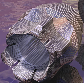
Figure 1. GE 90 engine Turbine Center Frame, meshed semi-automatically in GFEM using custom sweep tools. (Courtsey: Tata Consultancy Services, copyright reserved)

Figure 2. GE90 engine. Combustor Diffusor Nozzle. Meshed semi-automatically in GFEM using custom sweep tools. A bunch of shell-solid connections and pasted shells on solids visible in the model. (Courtsey: Tata Consultancy Services, copyright reserved)

Figure 3. GE 90 engine. Turbine Rear Frame.Meshed semi-automatically in GFEM using custom sweep tools. (Courtsey: Tata Consultancy Services, copyright reserved)
This will be part of the dependent project Geometry Preparation . A more detailed discussion will be soon included here.
This problem can be tackled in two ways.
Firstly, triangular elements can be swept to produce prismatic elements if they are both supported by ANSYS and UGFEA and do not have a performance problem.
Secondly, a manual edit feature may be used to correct meshes with transition elements so as to create all-quad-meshes. If this is opted for, it is part of the project, Manual Mesh Edit
A third option, for a long term plan, is to create a 2D mapped meshing function that produces all-quad-meshes.
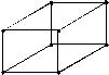
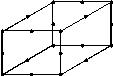
The hexahedral elements that UG/Scenario will support for UGFEA and ANSYS will be essentially isoparametric brick elements. The 2 basic type of elements that the mesher will support are:
Fig4.8 Noded Trilinear Brick Fig5.20 Noded Quadratic Brick
UGFEA Hex Elements : CHEXA element caters to both the trilinear and quadratic formulations and supports even p-type elements.[3]
ANSYS Hex Elements : SOLID 64 , which is the trilinear brick will cater to anisotropic material too. SOLID 95 is the 20 nodes quadratic element. This element however does not cover anisotropic materials. ANSYS p-elements have different signatures, and these need to be supported too, if we vouch for p-elements.[4]
UG/Scenario will however need to have 2 neutral elements to be able to support these types:
Both these elements will have 3 DOFs/node (UX, UY, UZ).
To begin with it is important to note that since we are primarily planning to develop a mapped mesher based on a sweeper, the strength of it lies largely in the functionality of the sweeper. Let us try to figure out first what attributes make a powerful sweeping mechanism. Next we will discuss some popular sweep techniques equipped with enhancements we have thought about.
The following features make an efficient sweep mechanism:
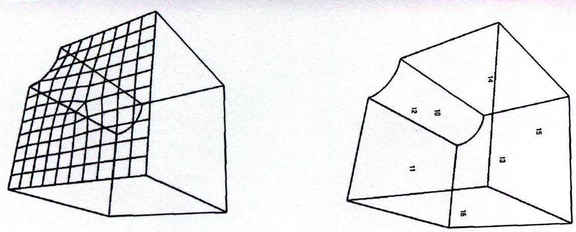
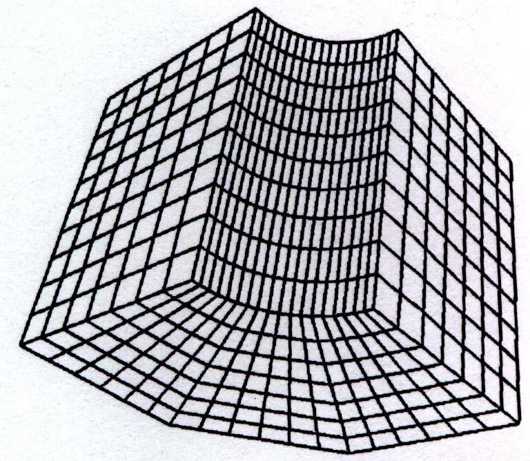
Figure 6. Sweep Mechanism1: A typical example of single source to single target sweeping. Face 11 is quad meshed and will be subsequently swept to form a hex-mesh. Face 15 is the target face.
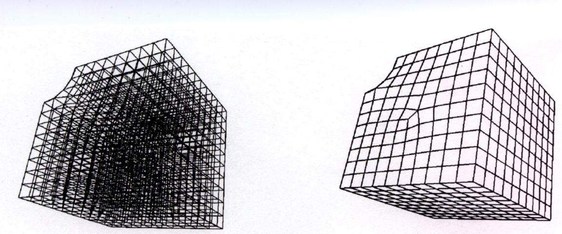
Figure 7. Sweep Mechanism1: The swept hexahedral mesh with both interior elements and exterior elements depicted.
Sweep Mechanism1:
This mechanism [6] works between 2 faces, a source and a target face, both connected completely by regular NURB surfaces. The faces may not be 4-sided, but they should not have open ends. The sweeper will read the quad-meshed (no tri's) face and start sweeping element by element till it reaches the next layer. It needs to read the quad elements of the source face orderly, say, in rows, or coloumns. This will ensure that at the creation time of every hex element (8 noded), 7 nodes are known directly. This means these seven nodes already exist. The position of the eighth node need to be determined. Four methods are proposed for determining the 8th node (vertex) a little later.
All new nodes created will be associated with the sweep faces. As soon as the eighth node is determined, the hex element may be checked for warp/twist/aspect ratio and corrected if required thru a corrector-predictor algorithm (preferably the Hughes-Liu algo). However, the performance criteria need to be checked.
The sweeper will work based on both element size and element number on the sweep faces. It will use the element size input directly as the default element size for determining the element thickness in the sweep direction in each layer. For a number entry, it will determine the element size based on the shortest edge length of the sweep faces connecting the source and target faces.
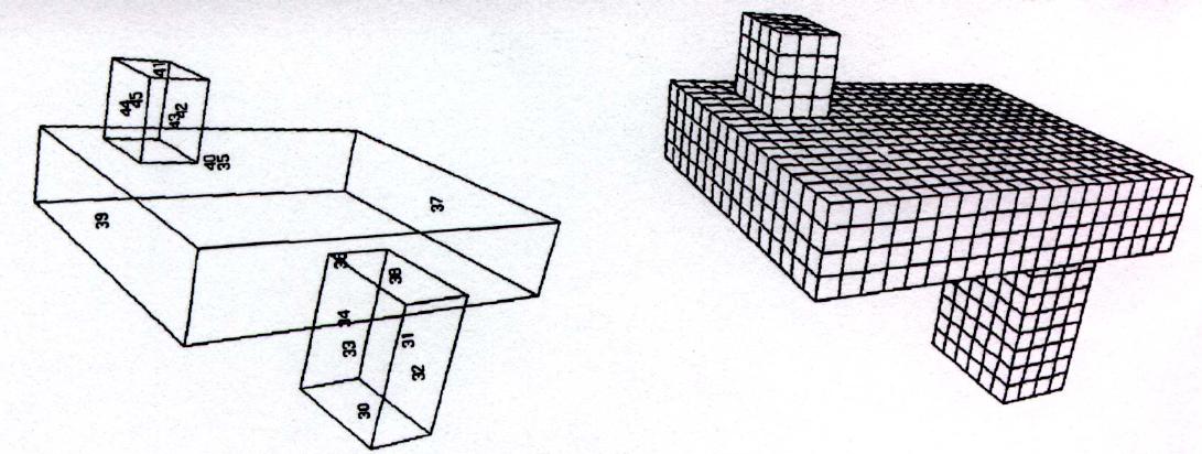
Figure 8. Sweep Mechanism 2: Single source multiple target faces. The single source face is 36 (bottom face of the bigger block), the target faces are 41 , 35 and 30. The sweep proceedes bi-directionally to the 2 target faces at the top and one at the bottom. Note the face connection constraints.
Sweep Mechanism2:
This mechanism [6] works between one source face (quad-meshed) and multiple target faces. The mechanism works exactly similar to the earlier one except for the fact that it is limited by multiple faces. See example
This sweeper will also need a similar method to determine the last vertex node ("eighth node"). It can contain the same corrector-predictor, face node and element - geometry associativity and can work based on both "size" and "number" the same way as mechanism1.
Sweep Mechanism3:
Along the lines of SM1 and SM2, this tool will work between multiple source faces to multiple target faces. [8] The sweep function is just an extension of mechanism2 and is described in detail in ref 3. This can be thought of as a long term need and can be easily implemented as an enhancement of SM2.
The relationship between source and target faces can be defined by the following constraints
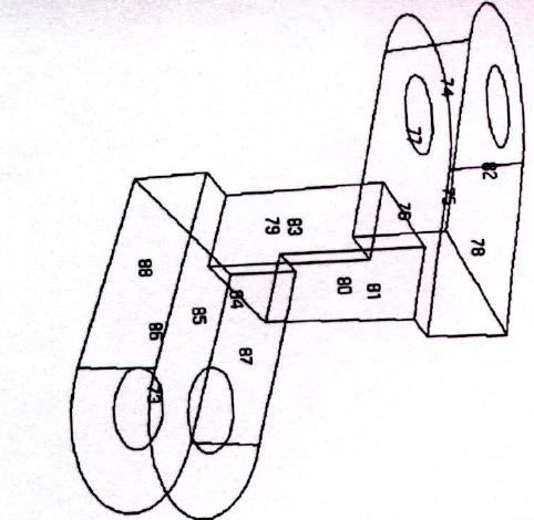
Figure 9. Sweep Mechanism 2: The single source face here is 88. The target faces are 87, 77 and 82.
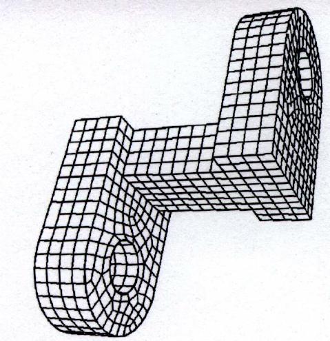
Figure 10: The resultant Hexahedral mesh at one go.
The relationship between multiple target faces can be defined by the following constraints
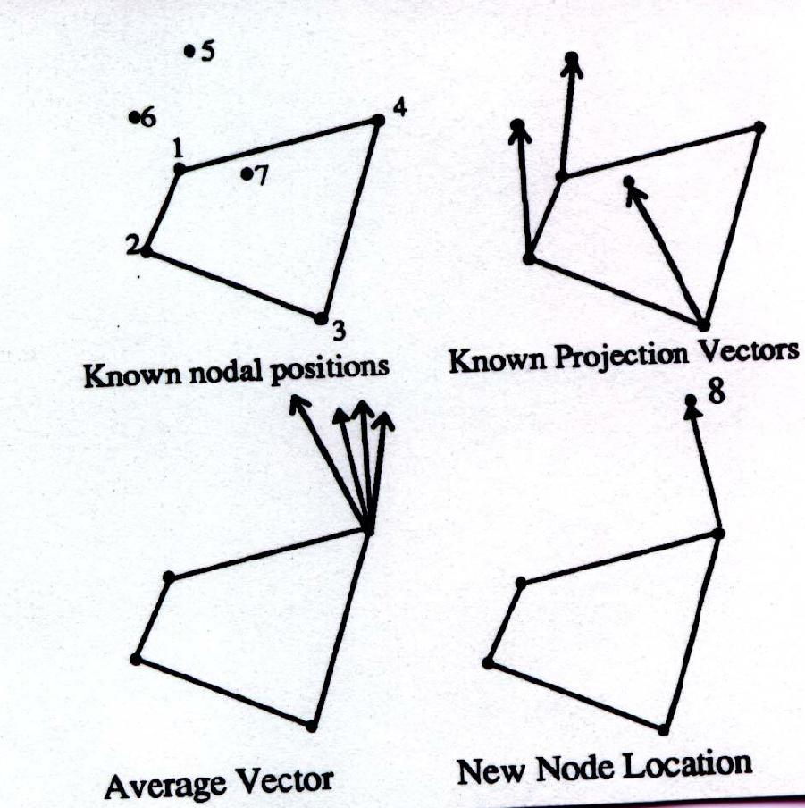
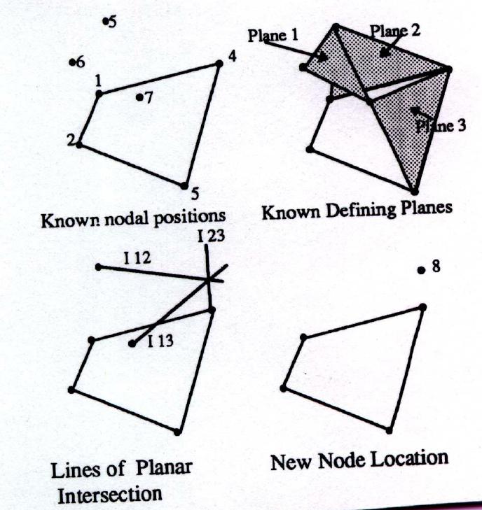
Figure 11. Average nodal vectors to determine the eighth node.
The resultant mesh.
Figure 11 describes the most conventional way to determine the unknown element vertex. The source quad element in the figure has nodes 1 - 4. Edges 1-2 and 2-3 lie on the solid edge. Using the default element size/number vectors are drawn at nodes 1, 2 and 3. The resultant nodes 5, 6, and 7 are pushed to lie on the bounding faces (using the face natural coordinates u,v). Now we are confronted with a question
How do we determine the location of the unknown hex vertex, node 8 ?
The most standard technique is to average vectors 1-5, 2-6 and 3-7 to get node 8. The same is repeated for the next element and so on. Thus, we can see, in the layer-by-layer, element-by-element (LBL-EBE) meshing approach, at a given time, 7 vertices of a hex are always known, the unknown 8th vertex can be determined following this method.[6]
The resultant mesh, however, as seen in Figure 11, produces a distorted mesh very often.
METHOD II:
The imaginary volume covered by this would-be-hexahedral can be mapped in a natural coordinate system by an isoparametric tri-linear brick (8 noded). The shape functions of this element can be used efficiently to obtain the 8th node location mapped back in the original coordinate system.
Ni = 1/8(1 +/- zi) ( 1 +/- eta) (1 +/- zeta) .....(1)
are the i-th shape functions of the tri-linear hex and zi,eta.zeta are the natural coordinates [10].
This is expected to produce a better mesh and had been used successfully as a GFEM UFUNC enhancement to mesh GE 90 engine assemblies as described in Figures 1-3 [5].
METHOD III:
A method that has recently been used quite successfully is the 3-planar intersection method [6]. As explained in Figure 12, 3 planes are defined between nodes 1-5-4, 7-5-4 and 5-6-7. I12, I23 and I13 are the lines of intersection of these planes. These lines meet at a unique point. This is the best spot for node 8. The resultant mesh, with this node locator scheme clearly reveals the improvement.
Figure 12. Planar intersection method. 3 known planes intersect to give
node 8. The resultant mesh.
METHOD IV:
A recent method to locate interior nodes by a Background Mesh Interpolation sweeping mechanism ( BMSweep) [7] uses the concept of "boundary ribs" and produces fairly efficient hexahedral meshes with minimum distortion.
It's apparent that a more detailed investigation would be necessary to identify the best of all these methods considering development efforts, flexibility, robustness and maintainability.
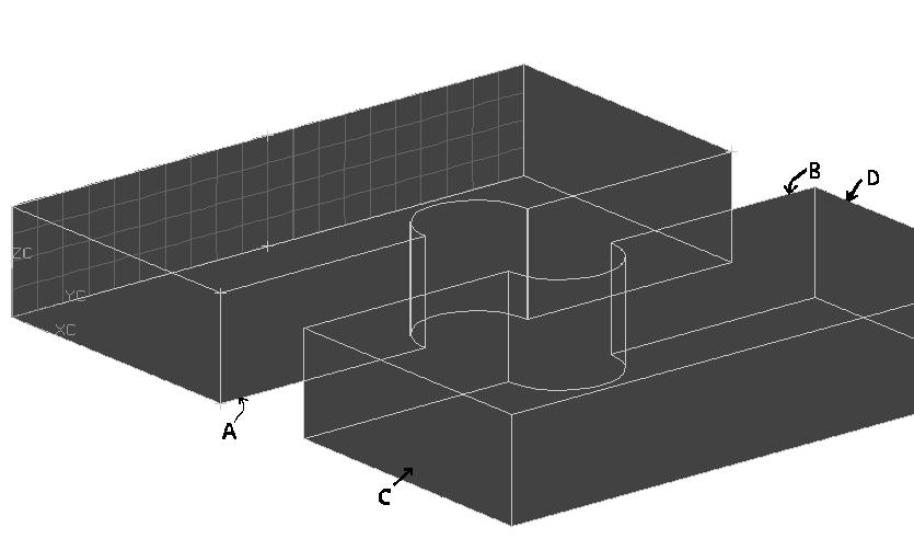
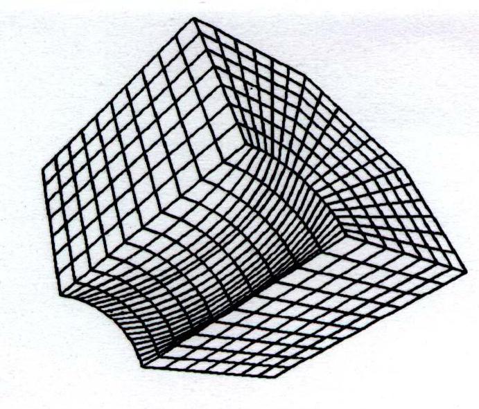
Figure 13. Split plate with a hole considered for 3d mapped meshing. The solid is split into 2 volumes 1 and 2. The first volume/body is first sweep meshed with the quad-meshed face swept upto face A. The hex-mesh face A is now copied to face B which is used to sweep volume/body 2.
This tool would be necessary to maintain continuity of hex meshes ultimately leading to a good connection. Let us take an example as described in Figure 13. Suppose the user first meshes volume 1 and logically wishes to mesh volume 2 in the following sequence. These volumes have resulted due to a model splitting. He needs to project face A of the hexed meshed volume 1 onto face B of the hex meshed volume 2. So we need a tool that projects the nodes of hex-meshed face A of volume1 to face B. No new set of nodes will be created, but the same set of nodes will be linked to face B. So both face A and face B will, at this point, contain the same node set.
Next, the tool will use these projected nodes to create a quad mesh on face B. This quadmesh generator could be an enhancement or a figment of the existing mesher. It needs a some attributes though:
These attributes need to be added to the quad mesh in Scenario. This may be treated as enhancements covered by the project Enhance Quad Mesher.
We now know how to project a hex-meshed face to a neighbouring cut face (of equal size). But we still have not answered the question -
How do we connect hex-meshes across split volumes ?
Let us try and answer this now. We have 3 options
OPTION I:
Let us refer to the earlier example in Figure 13. After the projection is done to face B, we have for volume 2, a source face already quad-meshed and a target face. So volume 2 is now ready to undergo the sweep. The Sweep Mechanism, after it creates the hex-mesh on volume 2, will read the source quad-mesh. If it finds that the source quad-mesh was a copied one, it will do the following
This ensures that there is only one solid now with one hex-mesh and the history of splitting/meshing/gluing is all lost.
So the bottomline is will have a smart sweeper that glues split volumes as it sweeps them.
The solid splitting and gluing functions will be part of the Geometry Preparation project.
Why is it important to glue solids as we sweep-mesh ?
This can be the source of some debate. It may be important to glue solids as the sweeper moves from one to another because of the following reasons:
(Refering once again to figure 13)
If the solids are moved after the split such that they are outside the tolerance now, or if face B of solid 2 is separately meshed the sweeper will not glue them. So in the process the user is given an option to continue with his originally desired mesh plan or abandon it.
OPTION II:
The Sweep Mechanism can be enhanced to acknowledge projected nodes/quad mesh on solid faces (both sweep faces and target faces). This has the other advantage of very few split requirements. In our case (Figure 13), after we project the hex-mesh to face B (which now has a projected quad mesh), we can quad-mesh face C and sweep that to face D. The sweeper will produce a different mesh but acknowledge the quad mesh on face B. All quad meshes will be deleted after the sweep. In the end we get 2 hex meshes on solid 1 (solid 1 and 2 will be glued together during the second sweep).
OPTION III:
A crude way of connecting the hex-meshes on the split volumes (Figure 13) is to quad-mesh faces A and B independently, sweep volumes 1 and 2 independently and then do a node merge on faces A and B to connect the meshes. This would require a minor enhancement of the existing Scenario merge node algorithm (provide a merging by geometry selection option) and has the following advantage
The disadvantages are
The improvements of the Node Merge function will be treated as part of this project.
This is one of the most diffcult questions to answer. Clearly a debatable issue that apparently needs a lot of brainstorming still. Conceptually the UG/Scenario mesh update function currently works like this :
3D-2D-1D-0D with the exception
3D-Contact-2D-1D-0D
Let us focus on three issues here.
How do we support mesh update for split->sweep meshed->glued solids ?
The hex-mesh update functionality depends very much on the mesh connecting technique. Once the solid is glued, its history is lost. Now if this glued solid is modified (feature unsupressed or model dimension varied) it is virtually impossible to support mesh update. However, if different meshes are produced in the same glued solid (Mesh Connection, OPTION II) it may be still possible somehow to support update.
I invite more ideas here.
How do we support mesh update for multiple target sweep meshed solids ?
This is relatively simpler. If a target face or a sweep face changes, the sweeper basically remeshes the entire solid following all updated faces.
Incase we changed the Scenario mesh update behavior including a time stamp function, how would the 3D mapped mesh update behavior change ?
An update that recognises time-stamps may solve the problem of glued-solids. However, if we begin by supporting one update for the hex-mesh and then change over to a time-stamp based one in V17, that calls for too much of temporary work. The bottomline for the hex-mesher is have a good update or nothing at all.
For single solids however, mesh update can always be supported at low cost.
There are a number of ways this can be achieved.
Figure 10. ANSYS hex-tet interface (Courtsey: Ref [2])
ANSYS has recently introduced a way to achieve this thru transition pyramid elements [2]. With support from the volume splitting tools we are targetting for V16, this turns out to be the best option. However, John Whetstone informs that ANSYS can offer an interface to that only in V17 time frame.
Some of the other options that can be thought of is mesh transition volumes with a tetra mesher that acknowledges both tri and quad face meshes. The current ANSYS mesher in UG/Scenario (V16 ph 1) acknowledges tri face meshes. Could that be enhanced to acknowledge quad-face-meshes ?
1. The Element Controversy Continues, R Russel & V I Weingarten, CAE Journal, pp86, Nov 1995.
3. MSC Nastran Quick Reference Guide, V70, 1998.
4. ANSYS Elements Reference Maunal. Release 5.4. Ninth Edition.
5. TCS FEA Project Report for GEPS/GECRD. Vol 2.1996.
6. A Multiple Source and Target Sweeping Method for Generating All Hexahedral Finite Element Meshes, Lai Mingwu, Steven E Benzley, Greg Sjaardema and Tim Tautges, Proc. 5th International Meshing Roundtable, Sandia National Laboratories, pp.217 - 228, October 1996.
7. BMSweep: Locating Interior Nodes During Sweeping, M L Staten, S A Canann, S J Owen, Proc. 7th International Meshing Roundtable, Sandia National Laboratories, October 1998.
8. Automated Hexahedral Mesh Generation by Virtual Decomposition, DR White, Lai Mingwu, SE Benzley, G D Sjaardema. Proc. 4th International Meshing Roundtable, pp 165-176, Sandia National Laboratories, October 1995.
9. The Cooper Tool, Ted Blacker, 5th International Meshing Roundtable, pp 13-30, Sandia National Laboratories, October 1996.
10. Concepts and Applications of Finite Element Analysis, RD Cook, pp 181, 3rd ed, John Wiley, 1995.